The Knowledge to Know Mold Part

Ejector Leader Pin and Bushing

Usually, ejector leader is supported by 4 reset bars, but when the ejector leader is large and heavy, the reset bars will bend because of the weight of the ejector leader. In this case, the repeated-moving ejector leader will push on the ejector pin and ejector sleeve, resulting in a deadlock or damage, etc.

If adopte an ejection guide system which is composed of ejector leader pin and bushing, the accurate guidance of the ejector leader movement can prevent the above-mentioned situation from happening.

Ejector-Leader-Pin

Support Pillars

Support pillars is a cylindrical part which is arranged between movable platen and moving clamp plate.

In the process of injection molding, the mould is subjected to great filling pressure, and the movable platen will bend instantaneously under the action of the pressure. The amount of bending varies with the die structure and forming conditions. It is generally considered that the deformation is about 0.01 ~ 0.2 mm. When the bending is serious, the formed product will appear burr or size increase and other undesirable phenomena. In order to eliminate above unqualification, support pillars can be set to prevent the deformation.

Spacer Ring

Spacer ring is a part which is arranged between ejector retainer plate and ejector plate, so as to keep the support space of ejector pin flange thick.

The thickness dimension of the specer ring is finished to 4 + 0.02/+ 0.01, which corresponds to the dimension of the ejector pin flange 4 + 0/-0.02. It can support the ejector plate while ensuring the most suitable parallelism.

The stop ring is used between ejector plate and moving clamp plate to ensure that there is a gap between the ejector plate and the moving clamp plate, so as to prevent the debris of the runner or garbage from sticking between the ejector plate and the moving clamp plate, which affects the reset precision of the ejector pin.

The stop ring must be used in the mould which with high precision at the front end of the ejector pin.

Spacer-Ring

Fine Positioning Component

Since there is clearance between guide pillar and guide sleeve, it is necessary to use more accurate positioning parts to ensure accurate clamping.

If the corresponding positions of cavity and core do not coincide completely, the core insert wedge and the slide core will collide and cause breakage or abnormal wear, sometimes can also cause the forming product size difference and produce burr.

This can be avoided by positioning the corresponding positions of the cavity and the core and preventing their dislocation.

The components for positioning include tapered pin set, pin set, tapered block set, block set, side block set, etc. The precision and size of the precision positioning component can be selected according to the size and structure of the die. In general, it is necessary to use precision positioning block components when mold temperature is high.

Tapered Pin Set

Tapered pin set is assembled around the cavity, and is used for positioning when injection.

It is a circular structure, and the installation part is easier to process.

Tapered pin set is divided into standard type and parting surface bolt fixing type, bolt fixing type can be disassembled from parting side, this is easy to maintain.

Tapered Block Set

Tapered block set is most suitable for high temperature mould applications such as crystalline resin and engineering plastics. During the thermal expansion of the plate, the mating surface of the tapered block can be installed parallel to the thermal expansion direction to absorb the thermal expansion of the plate, thus ensuring the correct positioning function.

fine-positioning-component

Pin Set, Block Set

Pin set, block set are made by changing the angle A of tapered pin set & tapered block set into 0°, which is used for the positioning of precision moulds such as the connector and the electronic component. Because of many small and precise cores used in the mold of connector and the electronic component, the space between the cores is narrow, therefore precise positioning is needed to avoid collision between the cores. The clearance between pin and sleeve of pin set and block set is small, thus it needs more care in the processing and arrangement of holes.

Side block set

Side block set is installed on the side surface of die, it is convenient to assemble and disassemble, and mounting hole (slot) on die plate is easy to process. Because fit clearance is very small, please use precision guide pillar.

Mold-Plate

Guide Pillar & Bushing

Guide pillar and bushing are guide parts used for accurate positioning of core and cavity. If mold cavity is not accurate alignment positioning, it will damage core and other forming parts.

Usually four sets of guide pillars are installed at four corners of core of die, and bushing is set at the relative position of cavity of die. But sometimes,

according to the structure of mold, guide pillar and bushing are installed reversely.

If used with precision positioning parts (tapered pin set, tapered block set, etc.) , the alignment and positioning of cavity will be more precise.

Guide Pillar

Guide pillar is divided into flange type and straight bar type.

Guide pillar and plate are usually fixed by interference fit, so the fixed part of the guide pillar root is set as positive tolerance. The outer diameter of guide pillar working face is set to negative tolerance because of the gap and relative movement between guide pillar and bushing. In order to insert guide pillar into bushing smoothly when injection, the leading part of guide pillar will be processed, which is composed of cone surface and R angle at the top angle of guide pillar.

Bushing

Bushing is divided into flange type and straight bar type.

Bushing and plate are usually fixed by interference fit, therefore the outer diameter of bushing is set to positive tolerance. The inner diameter of bushing working surface is set to negative tolerance because of the gap and relative movement between bushing and guide pillar.

Pin-Point Gate Bushing

Pin-point gate bushing is the part that uses bush structure to replace gate when point gate is adopted.

The front hole of point gate will be worn by continuous injection process, and the shape of hole will be deformed and enlarged. But if use pin-point gate bushing, it is simply to repair by replacing mold part when wear increases.

In order to make the sprue of point gate better demoulding, it is necessary to process the inner surface of pin-point gate bushing with good roughness.


In addition, precision machining is required to prevent the surface from undercut.

Runner Lock Pin

In a three-plate die with pin-point gate bushing, runner lock pin is used to temporarily fix the sprue of the pin-point gate on the runner pusher and cut off the gate from the formed product.

The front end of runner lock pin is an undercut, and the sprue of point gate can be forcibly demoulded from pin-point gate bushing.

It is recommended that the shape of runner lock pin be selected according to the type of plastic and the size of the pin-point gate bushing.

The Flange of Runner Lock Pin

The flange surface of runner lock pin sometimes retains heat treated primary color.

Runner Flow Adjustment Pin

For multi-cavity mold and common mold, according to the balance of the runner, the resin filling time of each cavity is prone to deviation.

When filling time deviation, the usual response is to adjust the channel diameter, equalize the filling time. In order to adjust the diameter of the runner, it is necessary to ream the runner or divide the cavity into several inserts, but this is time-consuming and laborious.

The runner flow adjustment pin is a product that can be easily adjusted in the condition that it is assembled in a die.

It is recommended that this part be used in the mold of multi cavity, and common mold of different products.

Characteristics:

It can be adjusted from parting surface even in assembled status. It is suitable for flow adjustment in trial die.

When used in a multi-cavity die, it can not only ajust flow, but also cut off or re-connect the resin flow to a specific cavity.

When in application of common mold of different products, it can realize two functions of flow adjusting pin and runner steering pin.

Pin-Point Gate Bushing

Gate bushing is a part that allows molten plastic material to be injected from nozzle of injection molding machine into internal runner of mold. If nozzle contact part of gate bushing is not machined to a shape that is consistent with the spherical surface of the front end of the nozzle of the injection molding machine, plastic material will leak out during injection molding.

In addition, if gate sleeve is not hard enough, nozzle contacts will wear out in repeated contact during injection molding.

When formed product is taken out, the cooled solidified runner is taken out as scrap. It is suggested that draft angle should be set in runner design in order to release scrap from gate bushing smoothly.

However, if draft angle is too large, the diameter of runner will become larger and the cooling time will be lengthened accordingly. Therefore, it is necessary to choose an appropriate draft angle according to the type of plastic raw materials and the expected forming conditions. In addition, the inner surface of hole for runner should be machined to a good surface roughness to avoid undercut. If surface roughness is poor, there is a risk of poor channel demoulding during forming.

If the quality of gate sleeve is different, the flow rate and forming conditions of plastic material will change, and it will be difficult to carry out unified quality management of mold.

Locating Ring

The locating ring is a part used to quickly connect the center of injection nozzle with the center of mold gate bushing after the mold is installed on the injection molding machine.

Using positioning ring, mold can be quickly butted to injection molding machine when changing mold, and the time of adjusting mold can be greatly reduced.

In addition, accurate docking can also reduce damage of injection molding machine nozzle.

Slide Core, Guide (Separate Type)

Slide core is a common part of side core pulling mechanism, which is mainly used in the case of concave-convex shape or side hole on the outer surface of formed products.

Guide is a part which is installed on both sides of slide core to ensure the slide core block to move back and forth according to a certain track. Because it is surface contact with slide core, it needs to be machined with good precision and surface roughness.

In order to prevent sintering of sliding part, it is suggested to use self-lubricating plate on the bottom surface of slide core.

Small Slide Core Assembly

In general, guide, angular pin, slide core and positioning block are set as a set of components to use.

The small slide core assembly combines the functions of these four parts, which can reduce a lot of design and processing work.

Angular Pin

When injection molding, if there is concave-convex shape or side hole on the side surface of molding product, the solidified plastic product can not 

be demoulded normally because of the interference of mold core when ejection, thus side parting or slide core mechanism should be adopted.

The concave-convex shape of plastic products is mainly divided into two categories: the outer concave-convex and the inner concave-convex. The slide core mechanism with angular pin is mainly suitable for the outer slide core of plastic parts.

A good slide core mechanism should be simple in structure and reliable in action. When ejection, the angular pin drives the slide core to complete core-pulling under the guide of guide by means of the opening force. When injection, positioning block set is reset by means of the clamping force. The sliding stroke of slide core depends on opening stroke, length of angular pin and inclined angle.

Taperless Core Pin, Stepped Core Pin

Core pin is an umbrella term for a variety of parts forming the inner surface of plastic parts. It is usually used in forming inner hole or cylindrical shape of products. Core pin selection is mainly based on axis diameter size, full length size and step shape which are specified by the shape of forming products. When necessary, need to carry out the front end processing and flange processing.

Sometimes to facilitate the air-vent of the product slender structural parts (such as stiffeners, cylinders, etc.), mold will also use core pin.

Stepped core pin are mainly used to counterbore on plastic parts.

Taperless stepped core pin is mainly used to counterbore of plastic part which without draft angle.

Straight Center Pin

Straight center pin is a part which is used to form a convex hole part on the surface of plastic part. It is usually assembled and fixed on moving clamp plate. The front end shape of straight center pin is selected according to the shape of hole.

In order to ensure the accurate movement of ejector sleeve and straight center pin, please maintain regularly.

In addition, in order to meet the accurate movement of ejector sleeve and straight center pin, the use of ejection guide mechanism (ejector leader pin, bushing) is recommended.

Ejector Sleeve

Ejector sleeve is a tubular ejector used for ejecting the convex holes on the surface of plastic parts such as the casing of household appliances, and is matched with center pin.

The convex hole of formed product is tightly adhered to mold due to forming shrinkage. Therefore, a large ejection force is required when demoulding.

If ejector pin is used only, there will be white trace on the surface of formed product because of the excessive ejection force, and sometimes the convex hole may be broken and remain in the die.

In order to avoid above, the use of ejector sleeve is necessary.

By pushing the end face of the convex hole with an ejector sleeve, the whole part can be pushed out smoothly.

In order to improve the strength of ejector sleeve with small front diameter, it is sometimes necessary to set a step at the root of ejector sleeve.

To ensure the accurate movement of ejector sleeve and center pin, please maintain regularly.

In addition, in order to meet the accurate movement of ejector sleeve and center pin, the use of ejection guide mechanism (ejector leader pin, bushing) is recommended.

Flat Ejector Pin

Because round part and its matching mounting hole are easy to machine (especially to grind), the section shape of ejector part (ejector pin) is usually round.

For the forming of plastic products, sometimes rectangular cross-section of ejector pin will be used. For example, rectangular cross-section of ejector pin is obviously better than round ejector pin for connector products if regarding with mold structure.

The edge and corner of flat ejector pin (rectangular cross-section) are sharp, and it is usually necessary to make proper chamfering according to the inner corner shape of assembling square hole.

The rod diameter part of flat ejector pin is cylindrical, only the front part of the pin is ground into a square section. The connection of the square part and the round rod part is processed into a transition arc r. , which can alleviate the concentrated stress when it is compressed or bent, and is not easy to be broken when used.

Intermediate Ejector Pin

Intermediate ejector pin is different from common ejector pin. When using intermediate ejector pin, the flange can not be fixed on ejector leader to move along with ejector leader, but need to process a counterbore, and make a time difference during the pin movement, then the product can be ejected.

Using time difference to achieve ejection, can make the product automatically out of the runner, or 2 times ejection molding.

Ejector Pin, Stepped Ejector Pin

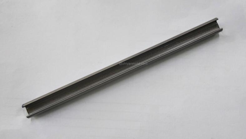
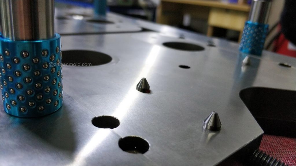
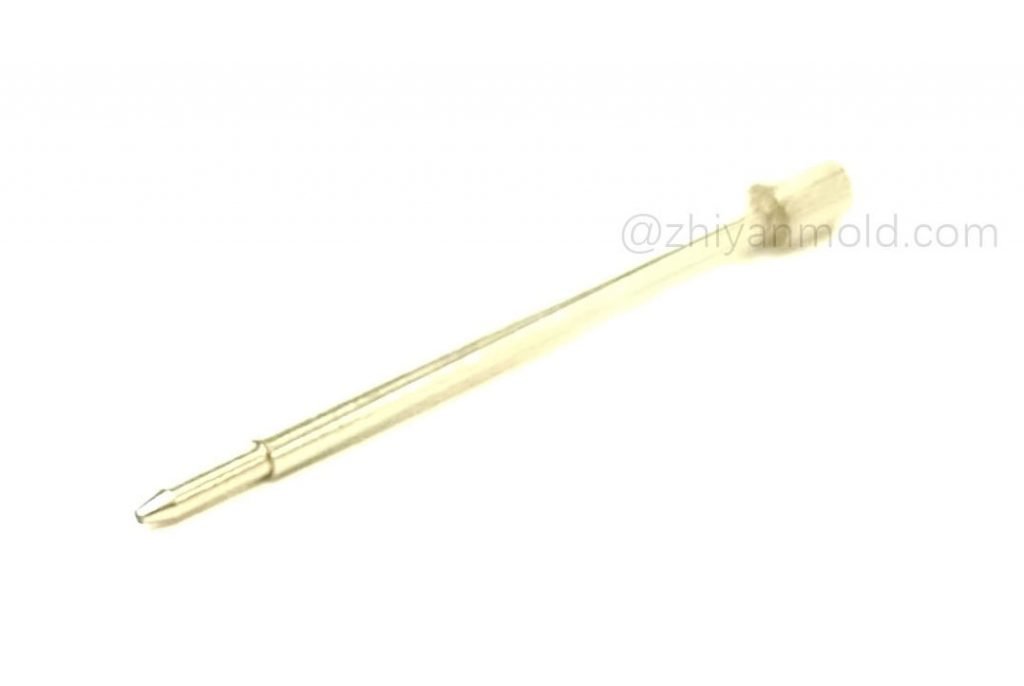
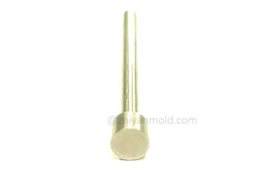
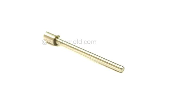
Stepped ejector pin is a part used to eject a formed product out of die.

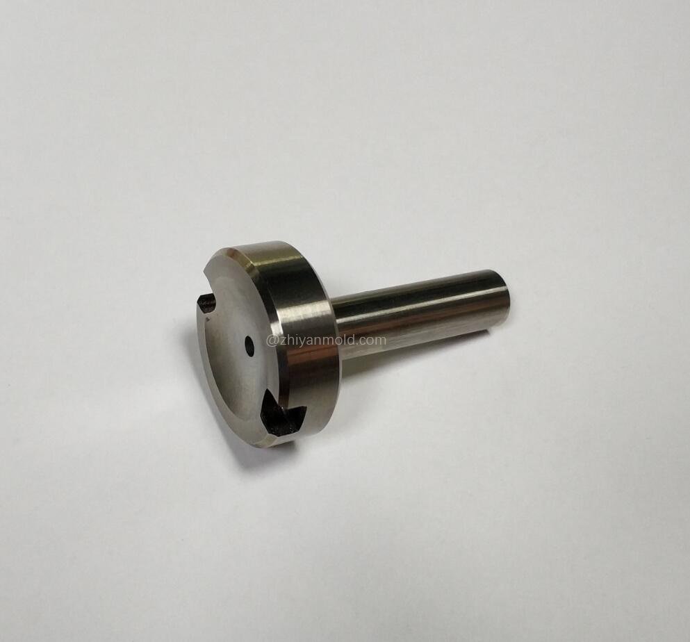
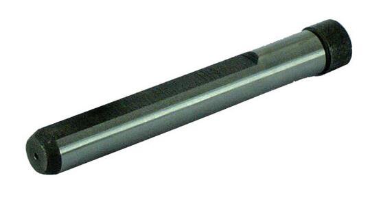
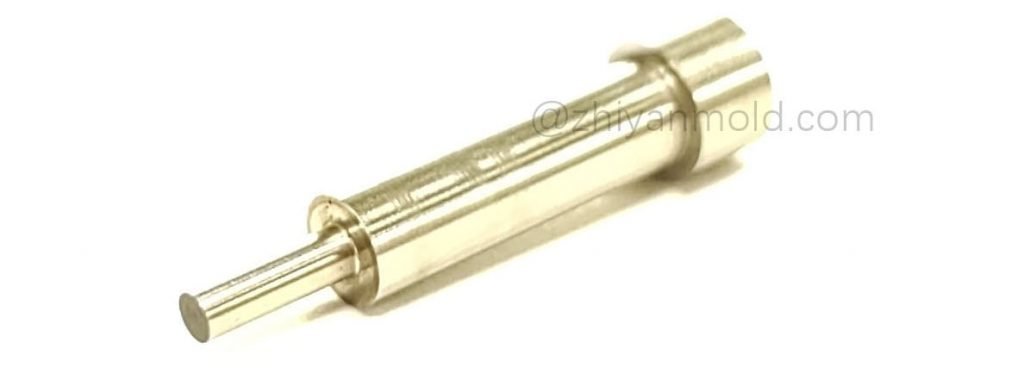
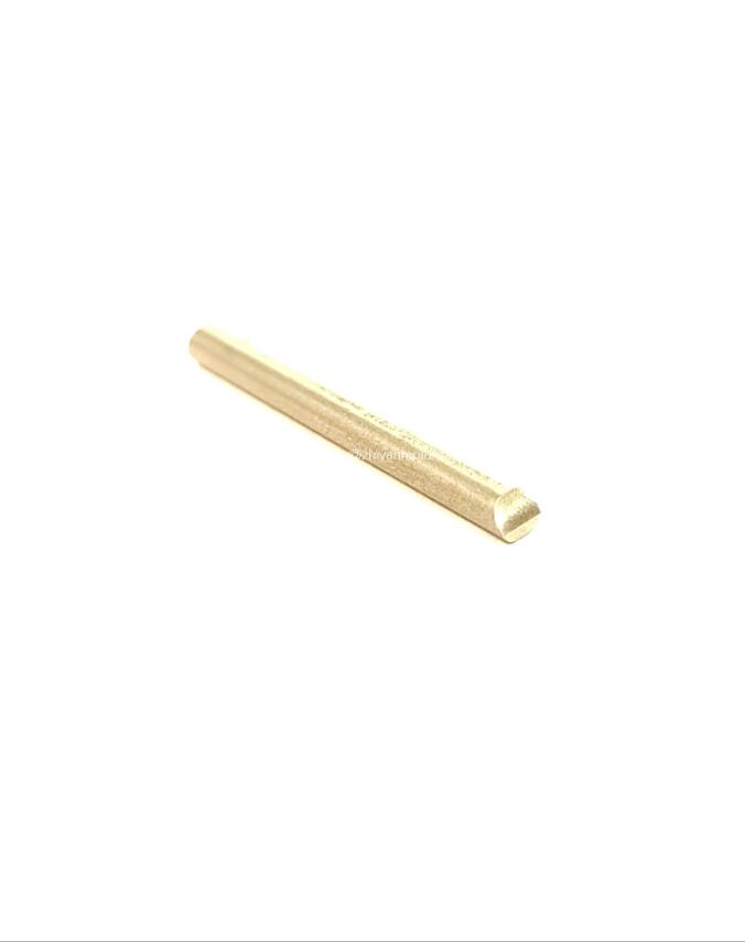
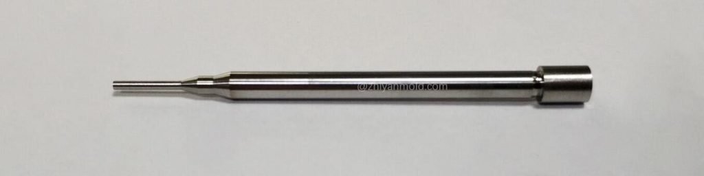
In order to eject a formed product pressed against cavity, an ejector pin of suitable thickness should be set evenly. The ejector pin may be broken or bent due to a compressive stress when it is pushed out. In order to prevent this kind of phenomenon, the ejector pin should have enough compressive strength and bending strength. Ejector pin with small shaft diameter is easy to bend and break when it is ejected from the formed part, in order to reduce the danger of this kind of phenomenon, ejector pin is usually designed as step type, and its body is one circle wider than the front end of the shaft, so as to increase the strength of ejector pin.

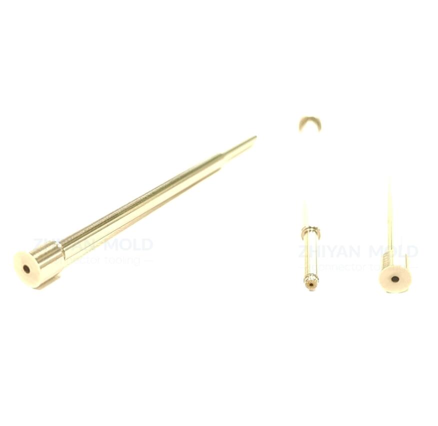
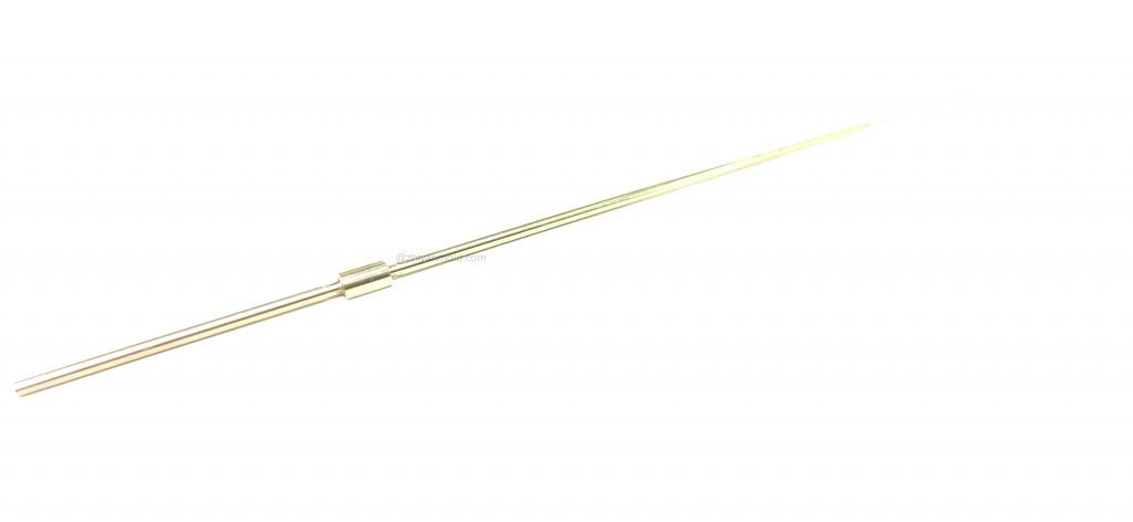
In addition, ejector pin is easy to wear when reciprocating motion, so it needs to use wear-resistant materials, and enhance the surface hardness. The surface of ejector pin must be smooth and clean, and the good diameter accuracy must be guaranteed.

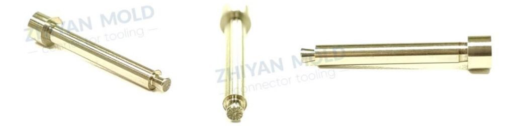
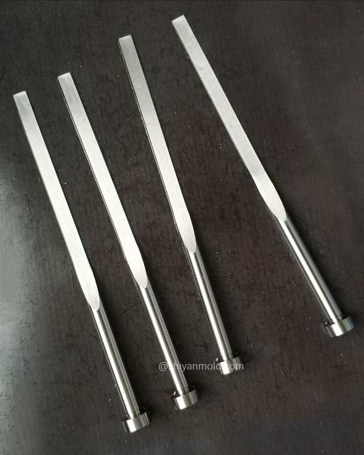
The degree of flexure is proportional to the square of the length of the small diameter part of stepped ejector pin (according to Euler’s formula). By shortening the length of the small diameter part of stepped ejector pin can ensure that it is not easy to bend.

The step-connection part should has a good transitional arc R, which can alleviate the stress concentration when it is compressed or bent, and is not easy to be damaged.

Front end processing

The front end of ejector pin is sometimes beveled or stepped according to the shape of the product. Similar to this kind of front end processing,

the flange of ejector pin needs an additional processing, which means milling off part, processing into anti-rotation shape, so as to ensure that the ejector pin does not rotate to change the diameter position of the front end shape.

发表评论

您的电子邮箱地址不会被公开。 必填项已用*标注

Let`s Have A Chat

Learn How We Helped
Top 100 Global Innovator Brands To Succeed